FLAT SLABS
INTRODUCTION
:
Construction
industry is being revolutionised with growing technology and innovation. Tall
structures have considerably reduced the problem of shelter but are considered
highly susceptible to seismic loads and uneconomical. Both the problems are
aroused due to huge weight of the building. Of all the structural members in a
building slabs are considered to be occupying higher area and the load of
the building is mostly contributed due to slab. In general for commercial areas
normal slabs are not been considered, as the spans between the supports are
more which leads to increasing in deflection and ultimately provision of huge
depth and percentage of steel is increased beyond the codal provision ,one
such solution to reduce the slab depth and provide economical design is flat slabs technology.
Flat
slab system is very simple to construct and is efficient . It requires
the minimum building height for a given number of stories. Such structure
contains large bending moment and vertical forces occur in a zone of supports.
This gives a very efficient structure which minimizes material usages and
decreases the economic span range when compared to reinforced concrete.
Post-tensioning improves the structural behaviour of flat slab structure
considerably. This is more acceptable concept to many designers. It is adopted
in some office buildings. The flat slabs are plates that are stiffened near the
column supports by means of „drop panels‟ and/or „column capitals‟ (which are
generally concealed under „drop ceilings‟).
Compared to the flat plate system,
the flat slab system is suitable for higher loads and larger spans, because of
enhanced capacity in resisting shear and hogging moments near the supports. The
slab thickness varies from 125 mm to 300 mm for spans of 4 to 9m. Among the
various floor systems, the flat slab system is the one with the highest dead
load per unit area. In general, in this type of system, 100 percent of the slab
load has to be transmitted by the floor system in both directions (transverse
and longitudinal) towards the columns. In such cases the entire floor system
and the columns act integrally in a two- way frame action.
Flat slabs are susceptible to punching. Under
extensive loading stress distribution lead to a concentration of stresses near
the column followed by a loss of strength across the connection. Existence of
flexural and minute flaws influence, as well, the behaviour of the flat slab
column connection zone. The influence is manifested by a diminished stress transfer
capacity.
Punching
of flat plates occurs without any warning and as a consequence of load boost
showing extensive cracking and large deflections. One of the solutions in order
to provide increase shear strength and higher rotational capacity at the flat
slab - column connection is be made by introducing shear reinforcement in the
control perimeter. In structural design of reinforced concrete flat slab –
column connection the main idea is to ensure adequate rotational capacity to
the connection zone, both for monotonic and cyclic loadings. This is made in
order to avoid a non-ductile, shear, brittle failure. By providing fair amount
of shear reinforcement a flexural failure is expected. Tough, flexural failures
can trigger post-peak punching shear failures due to extensive cracking. In
order to avoid progressive collapse of these structures, punching failure must
be ductile. Concrete transfers shearing force between two cracked interfaces,
in first phase, through the aggregate interlock mechanism. Mechanism compound
by friction, adhesive bonding and interlock between the protruding aggregates.
When another increment of loading is applied, the diagonal crack opens and the
previous mechanism disappear rapidly. In the next phase, the shear in mainly
transferred by the help of dowel effect of the reinforcement bars that cross
the cracked interface.
Types of FLAT
SLAB :
- Slabs without drop and column
head (Fig. 1).
- Slabs without drop and column
with column head (Fig. 2).
- Slabs with drop and column without column head (Fig.3).
- Slabs with drop and column head as
shown in (Fig. 4).
1.
FLAT PLATE
2.
FLAT PLATE WITH COLUMN HEAD OR CAPITAL
3.
FLAT PLATE WITH DROP
4.
FLAT PLATE WITH DROP AND COLUMN HEAD
WHAT ARE DROP PANELS AND COLUMN CAPITAL ?
Drop
Panels:
The 'drop panel' is formed by the local thickening of the slab in the neighbourhood
of the supporting column. Drop panels or simply drops are provided mainly for
the purpose of reducing shear stress around the column supports. They also help
in reducing the steel requirements for the negative moments at the column
supports. The code recommends that drops should be rectangular in plan, and
have length in each direction not less than one third of the panel length in
that direction. For exterior panels, the length measured perpendicular to the
discontinuous edge from the column center line should be taken as one half of
the corresponding width of drop for the interior panel.
Column Capital:
The column capital or column head provided at
the top of a column is intended primarily to increase the capacity of the slab
to resist punching shear. The flaring of the column at top is generally done
such that the plan geometry at the column head is similar to that of the
column.
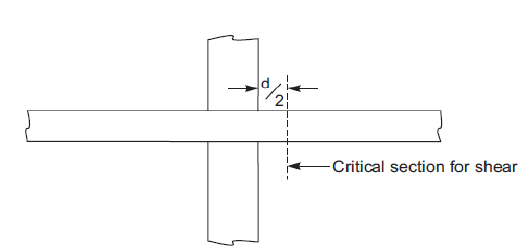
The code restricts the structurally useful portion of the column
capital to that portion which lies within the largest (inverted) pyramid or
right circular cone which has a vertex angle of 90°, and can be included
entirely within the outlines of the column and the column head. This is based
on the assumptions of a 45° failure plane, outside of which enlargement of the
support is considered ineffective in transferring shear to the column.
Advantages of flat slab :
1. Increases
speed of construction.
2. The
construction is simple and economical because of the simplified form work, the
ease of placement of reinforcement.
3. The plain
ceiling gives an attractive and pleasing appearance; in absence of beams,
provision of acoustical treatment is easy.
4. In general
flat slab construction is economical for spans up to 10m and relatively light
loads.
5. Compare to
the RCC less self-weight, which results in reduced dead load, which also has a
beneficial effect upon the columns and foundations
6. Reduces the
overall height of buildings or enables additional floors to be incorporated in
buildings of a given height.
Major problems in flat slab :
1. Slab column
connection does not possess the rigidity of the beam column joint.
2. Shear
concentration around column is very high due to the possibility of the column
punching through the slab.
3. Deflections
tend to be very large due to lesser depth of slab.
In the next article , i will show you the method of designing FLAT SLABS.